Inductive Loop Detector
Double-channel inductive loop detectors for precise, reliable vehicle detection in toll lanes, parking barriers and access control applications, with automatic environmental compensation.
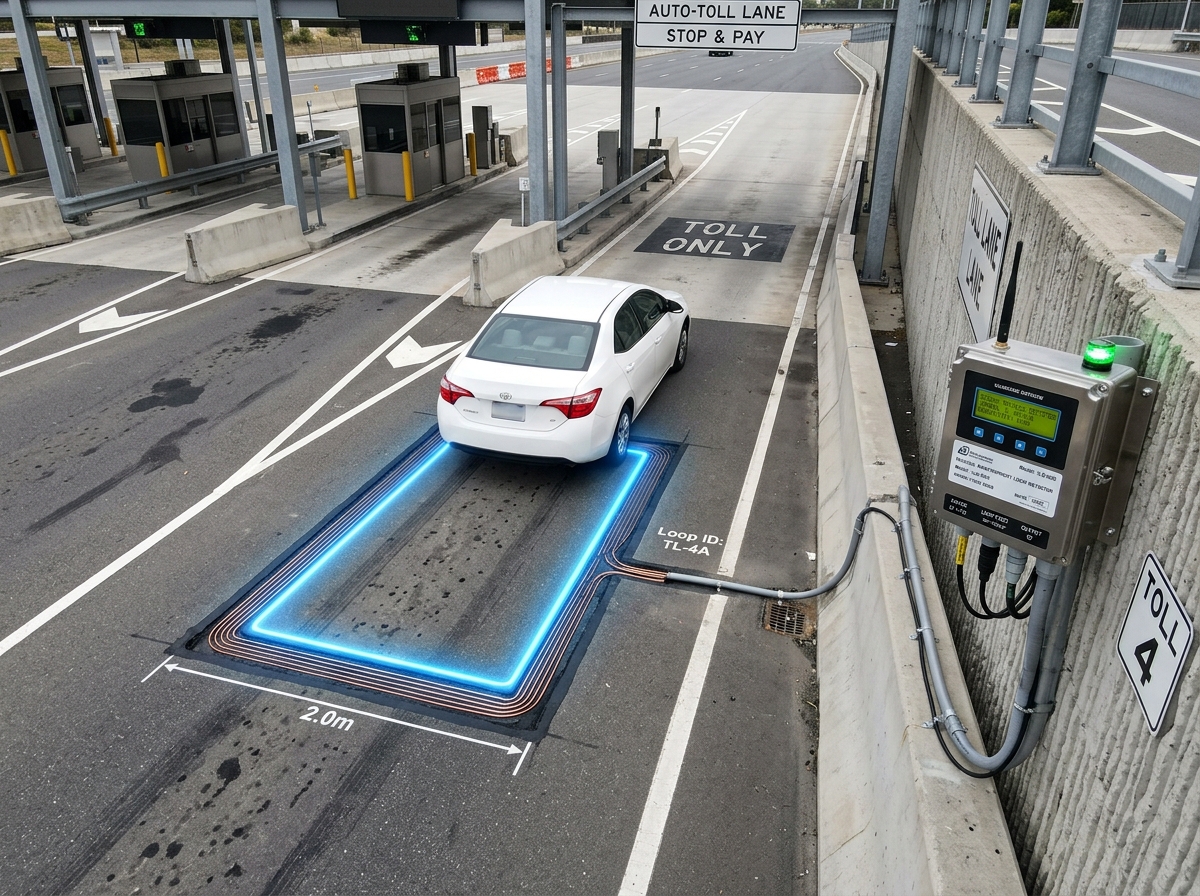
Precision Vehicle Detection in Road Pavement
Our double-channel inductive loop detector (LD100/LD101/LD102 series) is connected to a wire loop embedded in the road surface. When a vehicle passes over the loop, the detector switches an output relay.
Using microprocessor and surface-mount technology, the detector incorporates automatic environmental compensation, eight sensitivity levels, filter/extend/pulse options and LED fault diagnostics. It is compatible with most double-channel detectors on the market and is easy to set up and install.
- Double-channel design, compatible with most market standards
- 8 selectable sensitivity levels (0.01% to 2% L/L)
- Automatic environmental tracking & compensation
- Sensitivity boost for high-bed vehicle detection
- Filter option: 2-second delay prevents false triggers
- Extend option: holds output 2s after vehicle departs
- Permanent presence: detects stationary (parked) vehicles
- Reset switch for re-tuning during commissioning
- Power Fail Memory: 20 seconds
- Country of Origin: UAE
LD100 Series Technical Specifications
| Parameter | Specification |
|---|---|
| Power Supply (LD100) | 200–260 VAC, 50Hz, 1.5 VA |
| Power Supply (LD101) | 100–120 VAC, 60Hz, 1.5 VA |
| Power Supply (LD102) | 11–26 VAC/DC, 50/60Hz, 95 mA max |
| Presence Relay | Change-over contact, 0.5A / 220VAC (Fail Safe – normally energized) |
| Pulse Relay | Change-over contact, 0.5A / 220VAC (Non Fail Safe – normally de-energized) |
| Response Time | Approximately 120ms after vehicle enters loop |
| Indicators | LED: Power, Detect State, Loop Fault |
| Detector Tuning Range | 15–1500 µH |
| Loop Frequency | Approx. 23–130 kHz |
| Power Fail Memory | 20 Seconds |
| Environmental Tracking | Automatic Compensation |
| Protection | Loop isolation transformer with zener diodes and gas discharge tube |
| Connector | 11-Pin Connector on rear of unit |
| Dimensions | 80mm (H) × 40mm (W) × 79mm (D excl. connector) |
| Operating Temperature | -40°C to +80°C |
| Storage Temperature | -40°C to +85°C |
| Country of Origin | UAE |
LED Indicators
Illuminates when power is present.
On when a vehicle is over the loop or the loop is faulty. On reset, count the flashes and multiply by 10 kHz to find the loop frequency. For example, 6 flashes = 60–70 kHz.
On when the loop is open circuit or short circuit, giving a visual indication of a faulty loop.
LD100 Switch Settings
| Switch No. | Function | ON | OFF |
|---|---|---|---|
| 10 | Presence Relay Extend Time | 2 Sec | Off |
| 7, 8, 9 | Sensitivity 0.02% | – | S7/S8/S9 |
| 7, 8, 9 | Sensitivity 0.01% | S9 | S7/S8 |
| 7, 8, 9 | Sensitivity 0.05% | S8 | S7/S9 |
| 7, 8, 9 | Sensitivity 0.1% | S8/S9 | S7 |
| 7, 8, 9 | Sensitivity 0.2% | S7 | S8/S9 |
| 7, 8, 9 | Sensitivity 0.5% | S7/S9 | S8 |
| 7, 8, 9 | Sensitivity 1% | S7/S8 | S9 |
| 7, 8, 9 | Sensitivity 2% | S7/S8/S9 | – |
| 6 | Frequency | Low | High |
| 5 | Automatic Sensitivity Boost (ASB) | On | Off |
| 4 | Filter | 2 Sec | Off |
| 3 | Permanent Presence | On | Off |
| 2 | Pulse Mode | Undetect | Detect |
| 1 | Pulse Time | 1 Sec | 0.2 Sec |
Relay Functionality
| Relay | Contact | Vehicle Present | No Vehicle | Loop Faulty | No Power |
|---|---|---|---|---|---|
| Presence | N/O | Closed | Open | Closed | Closed |
| N/C | Open | Closed | Open | Open | |
| Pulse | N/O | Pulse closed | Open | Open | Open |
| N/C | Pulse open | Closed | Closed | Closed |
Presence relay is fail-safe: it reports "vehicle present" on loop fault or power loss.
Wiring
Relays are fail-safe; N/O and N/C contacts are marked on the detector's side label with the detector powered, tuned and no vehicle on the loop.
Diagnostics Troubleshooting Guide
Quick reference for diagnosing and resolving common loop detector issues.
| Symptom | Possible Cause | Solution |
|---|---|---|
| POWER LED not on | No power supply voltage on the input | Check that the power supply is correctly wired to the detector (Pins 1 and 2) |
| DETECT LED flashes erratically | Poor connection in loop or feeder; or crosstalk with an adjacent loop | Check all wiring, tighten terminals, check for broken wires. Change frequency: put the detector with the larger loop on low frequency and the smaller loop on high |
| DETECT LED randomly stays on | Faulty loop or feeder wiring; movement of loop in the ground | Check wiring, tighten terminals, check for pinched or bent wires and that the feeder is twisted. Check for cracks in the road surface near the loop |
| LOOP FAULT LED flashing | Loop inductance too small or loop is short circuit | Check for short circuit on loop feeder. If none, inductance is too small, so add more turns |
| LOOP FAULT LED permanently on | Loop inductance too large or loop is open circuit | Check electrical continuity with multimeter (< 5Ω). If too large, reduce number of turns |
Loop Installation Guide
Detector Placement
Install the detector in a waterproof housing as close to the loop as possible to minimise feeder cable length.
Cable Specification
Insulated copper wire, minimum 1.5mm². Feeder twisted with at least 20 turns per metre. Joints soldered and waterproofed. Use screened cable (screen earthed at the detector) where feeders may pick up electrical noise.
Loop Shape & Size
Square or rectangular, with min 1m between opposite sides. Normally 3 turns: 2 turns if >10m circumference; 4 turns if <6m. For two nearby loops use 3 turns in one and 4 in the other.
Avoiding Crosstalk
Place adjacent loops ≥2m apart and set different frequencies (one low, one high) to prevent interference.
Road Cutting
Cut slots ~4mm wide, 30–50mm deep with 45° corner cuts. Extend one slot from a corner to the roadside for the feeder.
Single-Length Wiring
Run one continuous wire from detector to loop, around 3 turns, and back. Twisting shortens the feeder, so allow extra length.
Seal the Slot
After placing loop and feeder wires in the slot, fill it with epoxy compound or bitumen filler.
Loop Placement
Do not put the loop below reinforcing mesh; keep it away from metal objects such as manholes and not too close to sliding gates.
LD100 Configuration
- Connect power to terminals 1 & 2, the loop to terminals 7 & 8, and the relay outputs as required.
- Extend (10): keeps the presence relay on briefly after the vehicle leaves to prevent a false undetect. Normally off.
- Sensitivity (7, 8, 9): for normal operation of 0.02%, switch all three off.
- Frequency (6): switch on to eliminate crosstalk or other interference. Normally off.
- ASB (5): boosts undetect sensitivity (e.g. at 1%, undetect is 0.5% with ASB off and 0.02% with ASB on) to keep high-bed trucks in detect. Leave off where possible.
- Filter (4): delays switching on when a vehicle enters the loop. Normally off.
- Permanent presence (3): for detecting a vehicle for days at a time, e.g. a parking bay. Off for normal use.
- Pulse mode (2): off = pulse when a vehicle enters; on = pulse when it leaves.
- Pulse time (1): off = 0.2 s, on = 1 s. Normally off.
In most installations all switches can be left off (toward the outside edge of the detector).
Powering Up & Testing
- Switch on the power and observe the lights on the front of the detector.
- Top light (power) must always be on.
- Middle light (detect) flashes a few times at power-up as the detector tunes. Flashes × 10 kHz = loop frequency (7 flashes = 70–80 kHz). If it stays on without flashing, check the loop or wiring.
- Bottom light (fault) indicates a loop problem: short circuit, inductance too small (add turns; 3 turns suit a 2m × 1m loop with 1.5mm² wire), inductance too big (rare; most loops are under 500µH, so reduce turns) or open circuit.
Typical Applications
Barrier Safety Loops
Detect vehicles under a barrier arm to prevent the barrier closing. An essential safety function.
Card Dispenser Arming
Trigger ticket/card dispensers only when a vehicle is correctly positioned.
Entry & Exit Loops
Detect vehicles entering or leaving toll lanes, car parks and controlled areas.
Vehicle Counting
Accurately count vehicles for occupancy management and traffic flow analysis.
Need Loop Sensor Expertise?
Site assessment, loop design calculations and full installation support.